Published: 02/10/2023 - Author(s): Rihn - Tag(s):
LED Fans on a Budget
Jank LED Props - Speedrun with coin cells, LEDs, and electrical tape
One cold winter’s day, we and a group of friends wanted to go busking in Boston. We picked a date, and the night before that date was upon us, we decided to make quick LED props for it. We camped out at the Edgerton 4-409 makerspace, jammed to our “Buskazoo” playlist (a compilation of songs we created to go busking with - which happens to include classics like the AmongUs trap remix and the Trucker’s HItch), and raided the electrical components shelves to create our made-in 1-day LED props.
Style 1: LEDs under wicks
From that late night session, Anika’s fans: through-hole LED’s (the kind often used for breadboarding, with two wire leads coming out of a plastic cap) taped to CR3032 coin cell batteries (the unfortunatley single use energy source for all these. They do come in rechargeable variants, though). Anika later soldered on switches between each LED and battery, so they can be turned on and off without having to untape the system. They were attached just under the wicks, which shielded the electronics from drops (the fan used was a spider web fan, as shown in this blog post on fan failure modes).
That same method (but without the carefully soldered button between the battery and the LEDs) were used to create an LED dragonstaff as well.
Style 2: LEDs embedded in the fan body
Also built from that late night session, my fans: pre-programmed through-hole LED’s set radially along each spine. It was quite a surprise how well the hole size and spacing I picked for this base incorporates the LEDs Edgerton had in stock. Check it out in action!
Here’s a look at the fans I prototyped. It serendipitously perfectly fit 3mm through hole LEDs 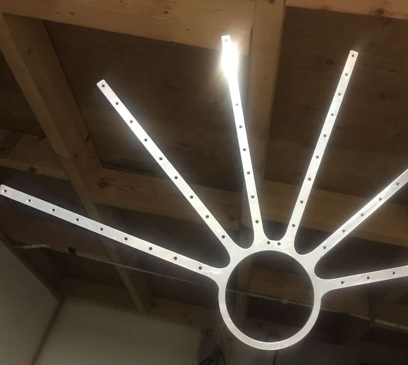
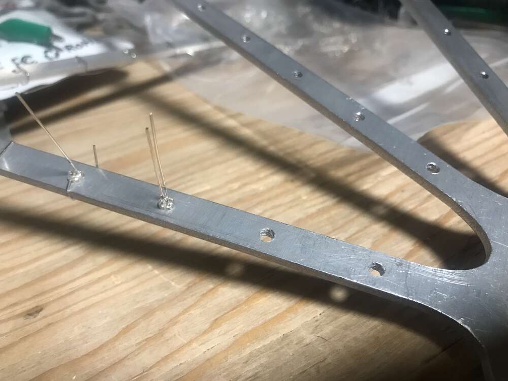
The leads were just long enough to wrap around the metal spine and hold itself there,
with the added benefit of putting the LED in contact with the fan’s conductive metal
frame. This was used as the ground plane connection. 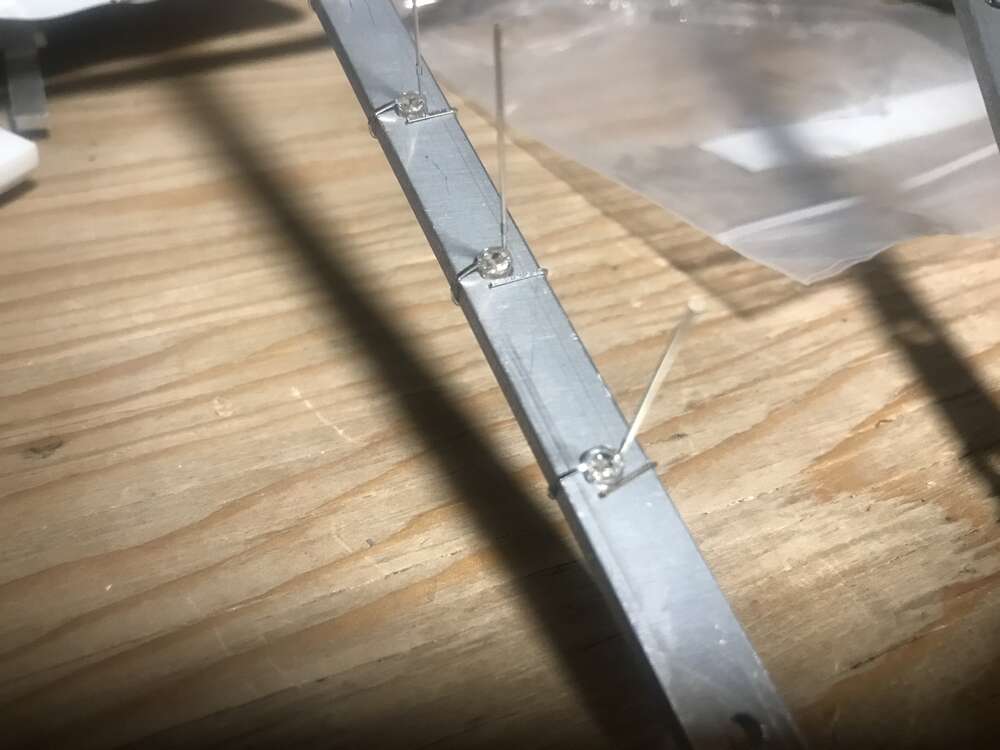
Soldering the positive side of the LEDs together meant there were no
external wires for a clean look without other wires or tape.
The LED is also visible from both sides due to resting in the hole! 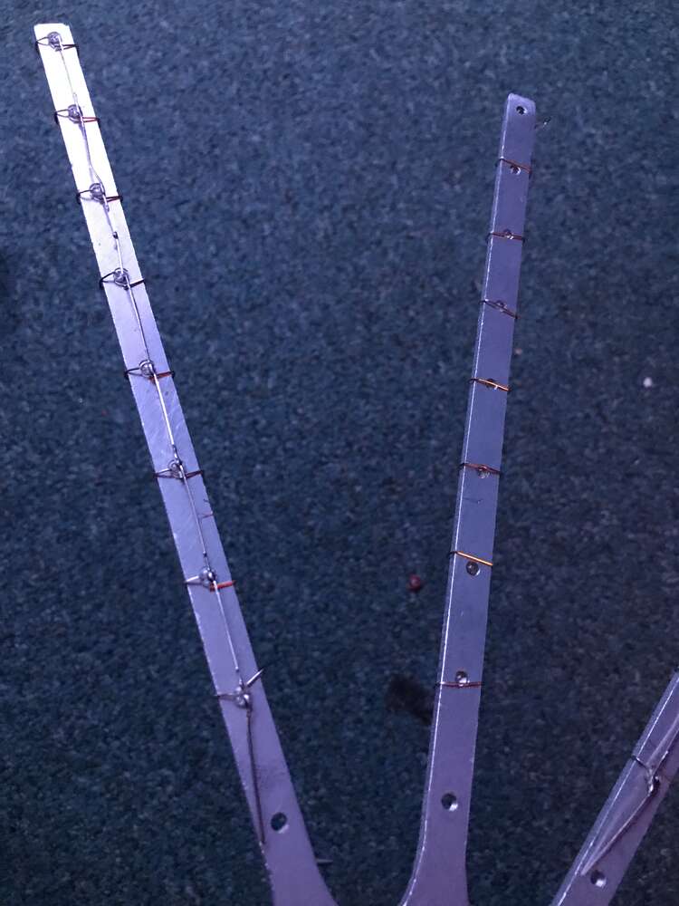
It looked spiky in the process! 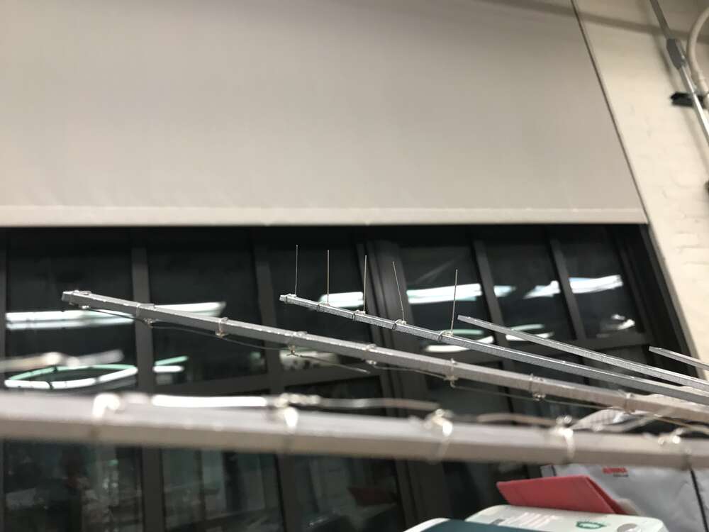
The soldering took a couple of hours, but it was important to create a reliable connection.The photo above shows how the LED slightly sticks out of the hole, and that distance is (usually) enough to prevent the positive lead and the ground plane from connecting. The metal fan wasn’t the best conductor, and each spine of LEDs needed its own battery attached to it. This was done via press fit with electrical tape, where the coin cell was slid underneath the LED lead so the negative lied on the fan frame.
Behind the Sparkles
The sparkly red effect was due to randomness of the LED’s built-in programming, where it’s meant to cycle through red, green and blue light. Since the LED’s are chained in paralled, if the LED’s get out of sync and one is programmed to be red while another in the chain is meant to be blue or green, only the red one shows. This is due to the red LED having a lower voltage drop, so current wants to go through those LEDs rather than the other ones. This was an unintended consequence, but created a beautiful sparkling effect.
Failure modes
The main failure mode was the fan taking falls that cause the positive leads to bend inward and touch the frame, as this would cause a short in that spine. The fix was to just inspect the spine that is no longer lit and re-bend the wires back in place. While an exciting application of the all metal fan frames, this particular setup does not seem robust enough to last.

